What is workholding?
Workholding is a critical part of any CNC operation. It might be stating the obvious, but while SmartBench is cutting, that stock material has to not move! Keeping that stock material secure is essential for:
Job reliability
Accuracy
Safety
Preventing damages to SmartBench
Spoilboard
A spoilboard is a disposable work surface mounted on top of the Y Bench, and sits under the stock material. We recommend using a spoilboard to prevent damage to the Y Bench if the tool cuts through.
Stock material
Stock material refers to the material you will use to produce your final piece.
Workholding
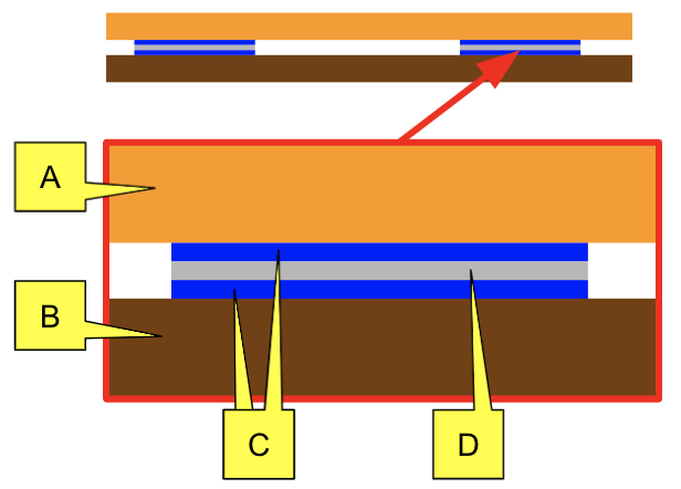
The spoilboard is secured onto the Y Bench, and then the stock material is attached on top. The X Beam then runs along both the spoilboard and the stock material, clamping them together during the job.
A: Y Bench
B: Spoilboard
C: Stock material
D: X Beam

What is it?
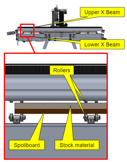
SmartBench features our patented material clamping approach. The X Beam (shown below) is split into two assemblies, and the material is clamped between them. Rollers allow the X beam to travel along the length of the material, providing support to the underside of the material where it is needed as it is cut.
We call this material clamping technology.
F: Clamping force

We have a video which explains this a little more here:
Traditional CNC machines follow a more traditional approach, which is to put rigidity across the entire workspace, whether it is used or not. But this makes them big, bulky, heavy and expensive.
SmartBench’s built-in material clamping technology provides the rigidity it needs directly at the cutting site. This allows it to be significantly lighter and more efficient, from a mechanical perspective, than the traditional approach.
General principles for the material clamping technology need to work
The material must be fixed to the Y bench
Beam clamping offers support to the material in the Z axis, but in most cases the material will also need to be fixed in the XY plane (onto the Y Bench). This will prevent the material from shifting as the beam travels along the Y axis.
Note that if the materials are heavy, the weight of the materials alone may be sufficient to keep the materials from moving. However we would always recommend fixing (if possible) to decrease the risk of materials shifting during a job.
Rollers must be positioned to provide material support
Large sheet materials will overhang along the sides of the Y Bench, and may sag in areas which are furthest from the X Beam.
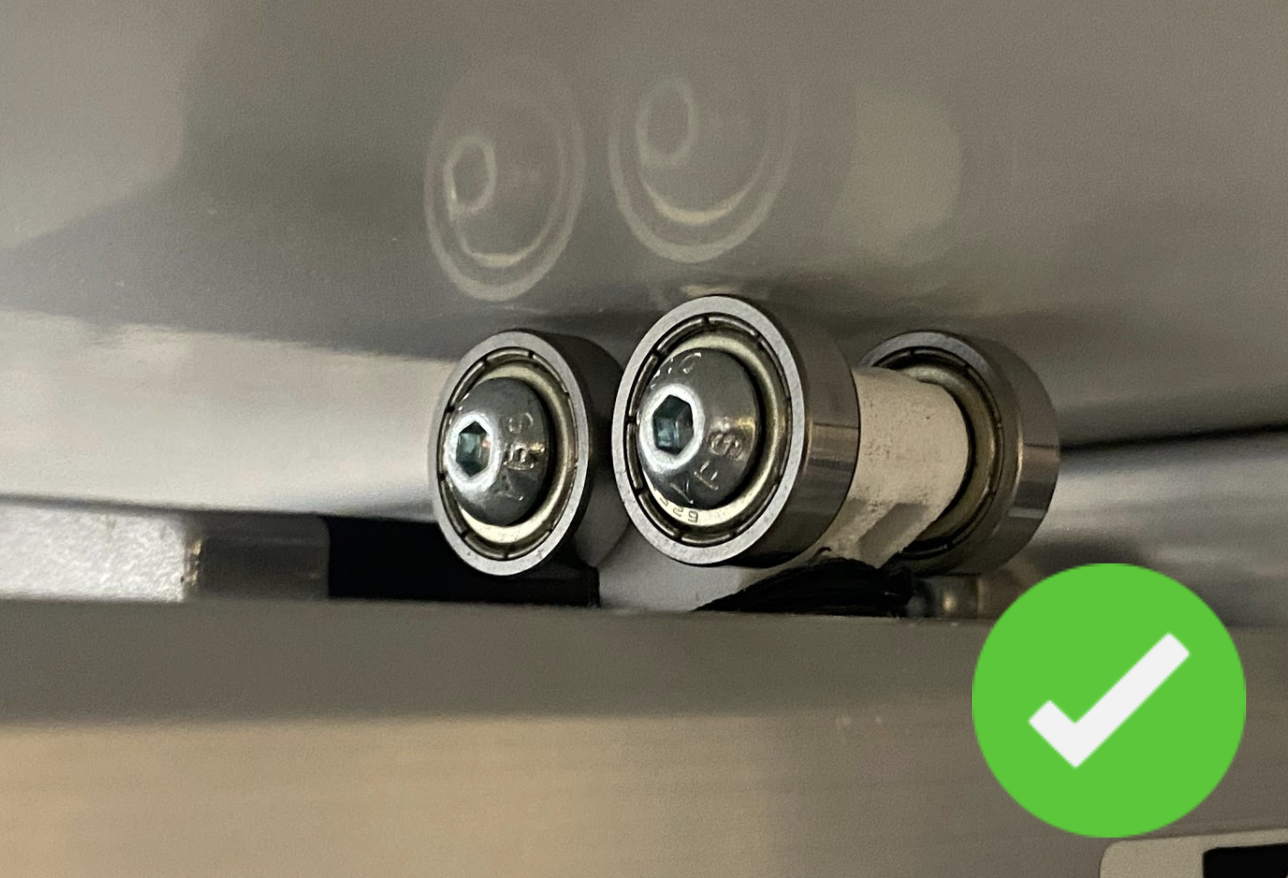
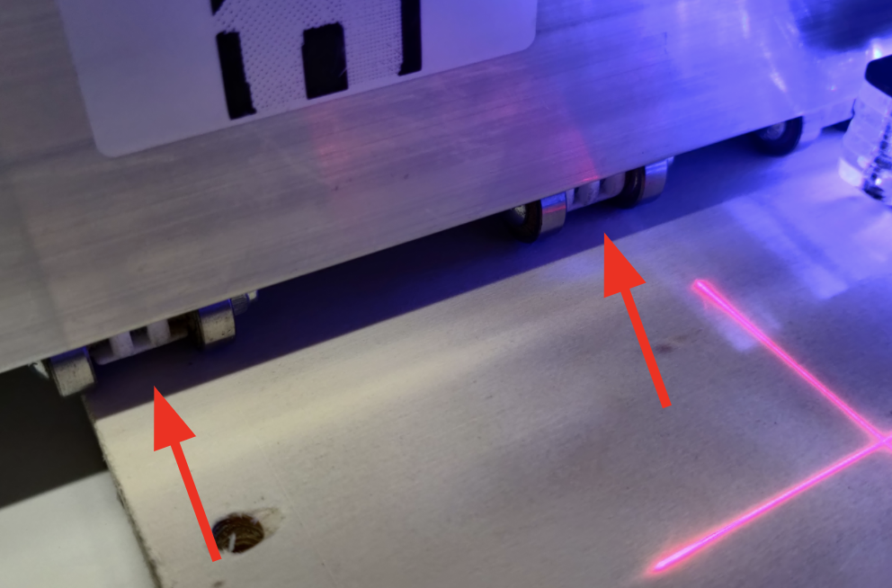
As SmartBench travels along the material it flattens and supports it with rollers on both the Upper X Beam and Lower X Beam. For the process to be accurate, rollers have to make full contact with both top and bottom surfaces throughout the job.
When you have positioned your materials, adjust the rollers so that they will always be in contact with the work surface and the spoilboard as SmartBench moves through the Y axis.
Rollers must travel easily across the workpiece, so ensure all contact surfaces are smooth and flat throughout the length of the travel.
We will go over this principle more in the sections on choosing a spoilboard, and supporting the Upper X Beam (particularly in the case of using offcut materials).
Secure clamping of the X Beam around the material
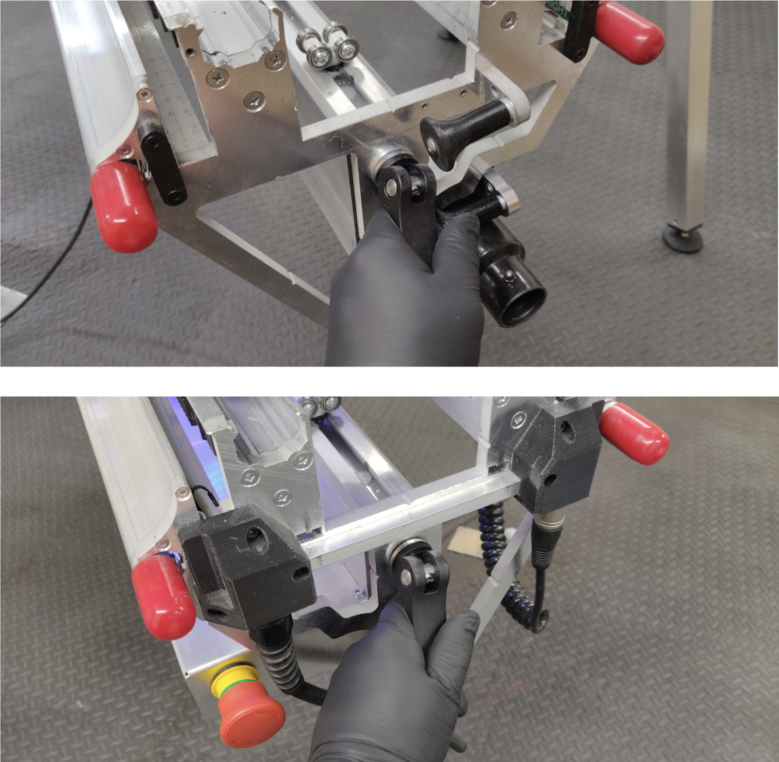
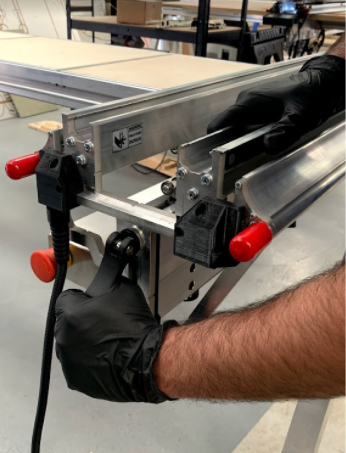
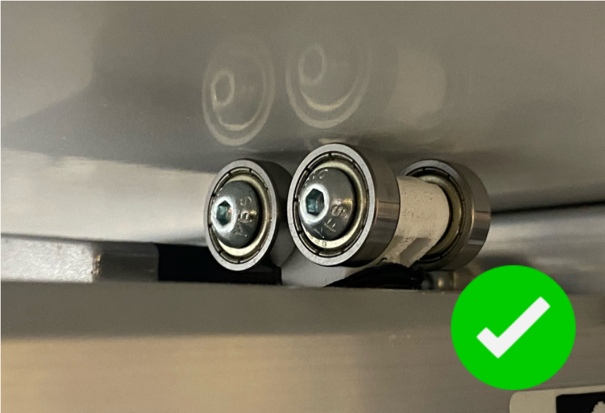
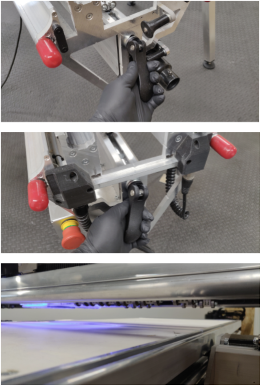
When you drop the Upper X Beam onto the material, ensure that the rollers are fully resting on the surface of your workpiece, evenly distributing the weight of the Upper X Beam onto the material surface.
Then, securely clamp the Upper X Beam to the Lower X Beam, using the two clamp handles at each end of the X Beam.
A spoilboard is a disposable work surface mounted on top of the Y Bench. It sits underneath the stock material and is clamped between the rollers of the Upper and Lower X Beams.
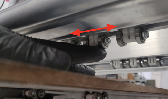
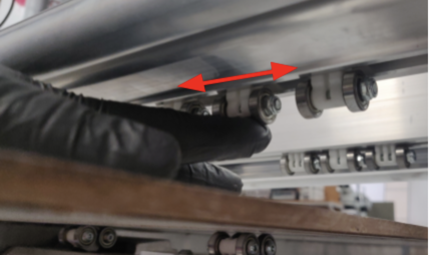
You can adjust the position of the rollers on the Upper X Beam by pushing them, so that they make contact with the spoilboard and stock material.
The spoilboard has three main functions:
Protect SmartBench from damage when the tip of the cutter breaks through the bottom surface of your work piece.
Become a large format work holding surface which can be easily removed when SmartBench is not in use.
Improve the surface finish on the underside of your workpiece.
Spoilboards improve the finish on your work by providing another solid surface for the cutter to work against as it breaks through the bottom of your stock material. |
How do I choose the correct spoilboard?
Many different materials can be used as spoilboards. When selecting a suitable spoilboard, it is important to choose something that is:
Rigid
Flat
Bigger than your stock material
Cost effective
Smooth – especially on the bottom
Ideally have a straight edge that can be aligned with the Y axis.
We recommend using a 6mm (1/4’’) or 9mm (3/8’’) double melamine faced MDF board. |
Important: use a smooth board!
The spoilboard MUST be smooth enough that:
The Lower X Beam rollers can make full contact with it throughout the entire job.
The X Beam can securely clamp both spoilboard and stock material firmly together, with no movement or unevenness during operation.
The beam rollers can run easily along the length of the spoilboard, with no resistance.
Top surface of spoilboard
The top surface of the board should be flat and smooth enough that the stock material:
Can be laid flat on top of it.
Still makes good contact with the spoilboard.
It is ok to reuse a spoilboard that has been cut into from a previous job, provided it meets these requirements.
Bottom surface of spoilboard
The lower rollers need to run along a flat and smooth surface. A smooth flat surface is essential to:
Prevent resistance which may cause the Y axis to stall.
Maintain finished part accuracy in the Z axis.
Use a material, which is:
Possible to use with SmartBench (see the list of materials below).
Flat.
Big enough for the job.
Appropriate for what you want to create.
These are common stock materials that work well with SmartBench:
softwood
hardwood
plywood
MDF
laminates
plastics
soft metals
Positioning and aligning of spoilboard is important as it will allow you to:
Align your stock material using spoilboard’s edge as a reference.
Prevent the moving parts of SmartBench interfering with the spoilboard during a job.
Unclamp the Upper X Beam, raise it high enough to accommodate the total thickness of the spoilboard and the stock material you are planning to use; then reclamp the Upper X Beam in the raised position to prevent it sliding down and locking the materials.
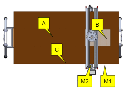
Position the spoilboard roughly in the centre of the Y Bench.
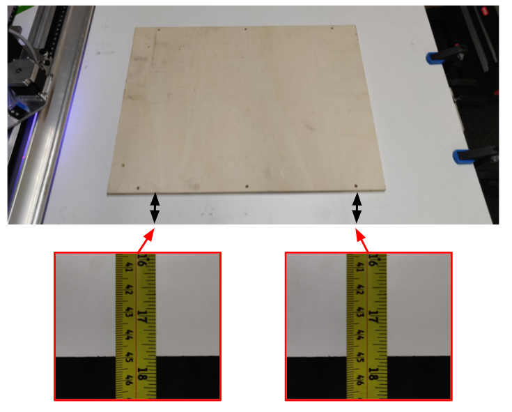
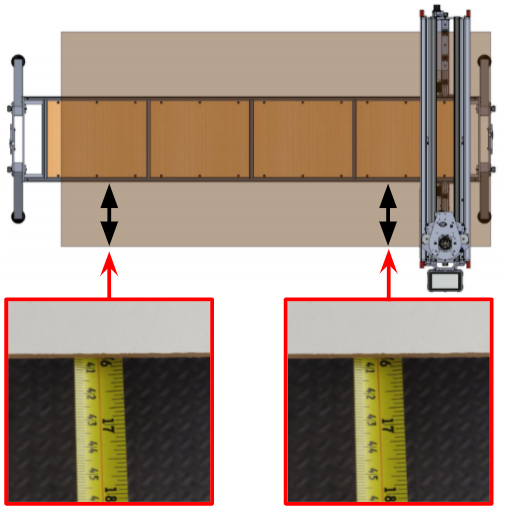
A: Spoilboard
B: Straight edge
M1 and M2: Measurement points

Using a tape measure align the spoilboard with the side of the Y Bench.
We assume the spoilboard has a straight edge, which we can use to align it along the Y axis. |
Measure the distance between the edge of the spoilboard and the side of the Y Bench at two points (e.g. M1 and M2), as far apart as possible.

Repeat the operation several times until the edge of the spoilboard is aligned with the Y Bench.
Positioning stock material
Position your spoilboard first, if you are using one and you have not done so already.
Unclamp the Upper X Beam, raise it high enough to accommodate the total thickness of the stock material you are planning to use; then reclamp the Upper X Beam in the raised position to prevent it sliding down and locking the material.
When positioning your stock material, make sure SmartBench can move within the work area without interfering with workholding components, e.g. clamps.
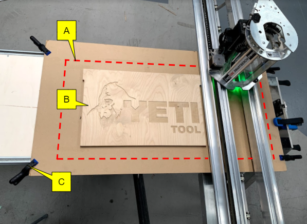
A: Work area
B: Stock material
C: Clamp
Aligning stock material
Option 1: referencing the spoilboard
First, position and align your spoilboard. Read the previous section to learn how to position a spoilboard.
Then, use the Y axis edge of the spoilboard as your reference for aligning the stock material.
A: Spoilboard
B: Stock material
C: Y axis edge
M1 & M2: Measurement points
Option 2: referencing the Z Head
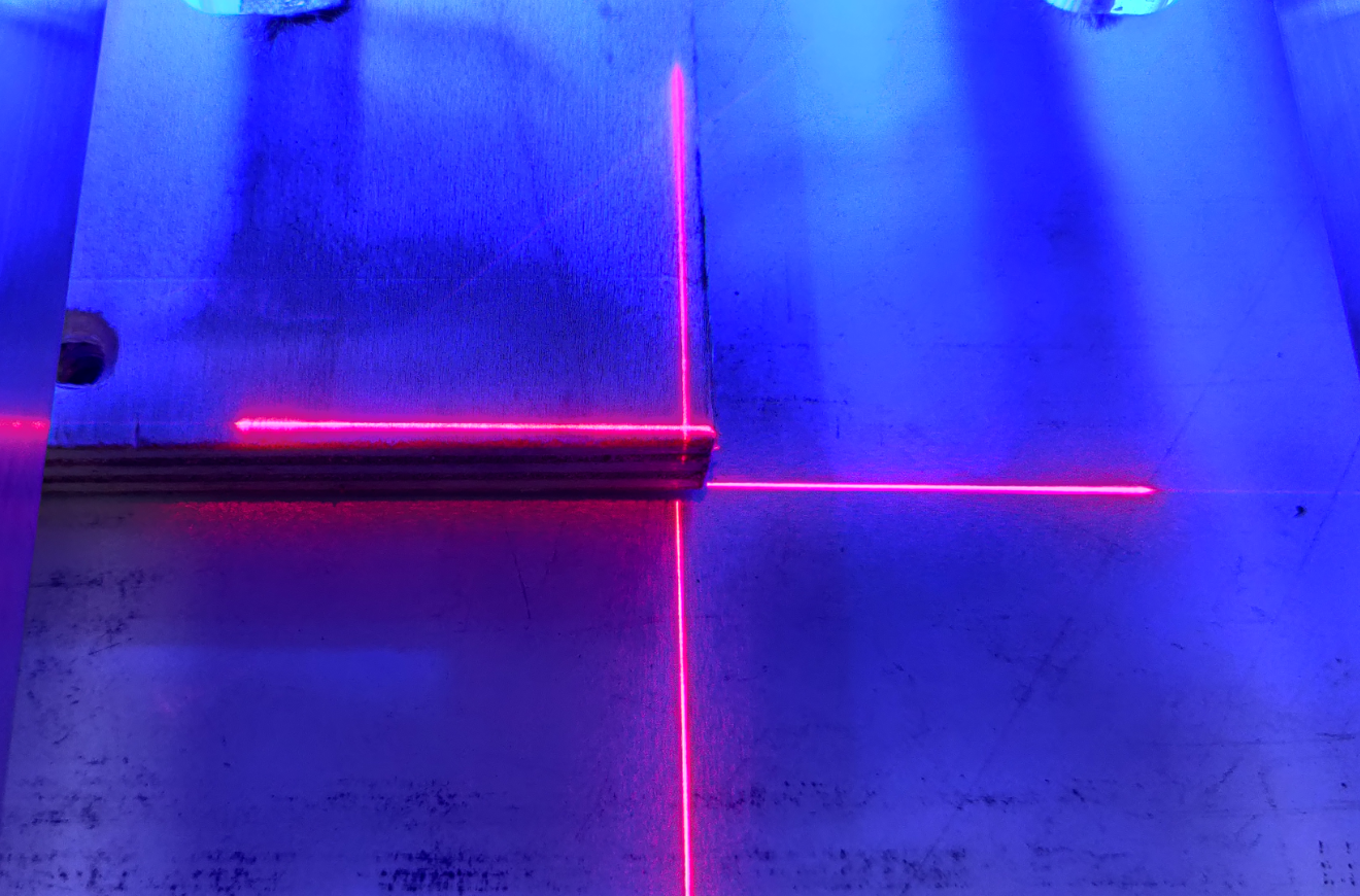
With SmartBench PrecisionPro, you can use the laser datum to align your offcut sheet material.
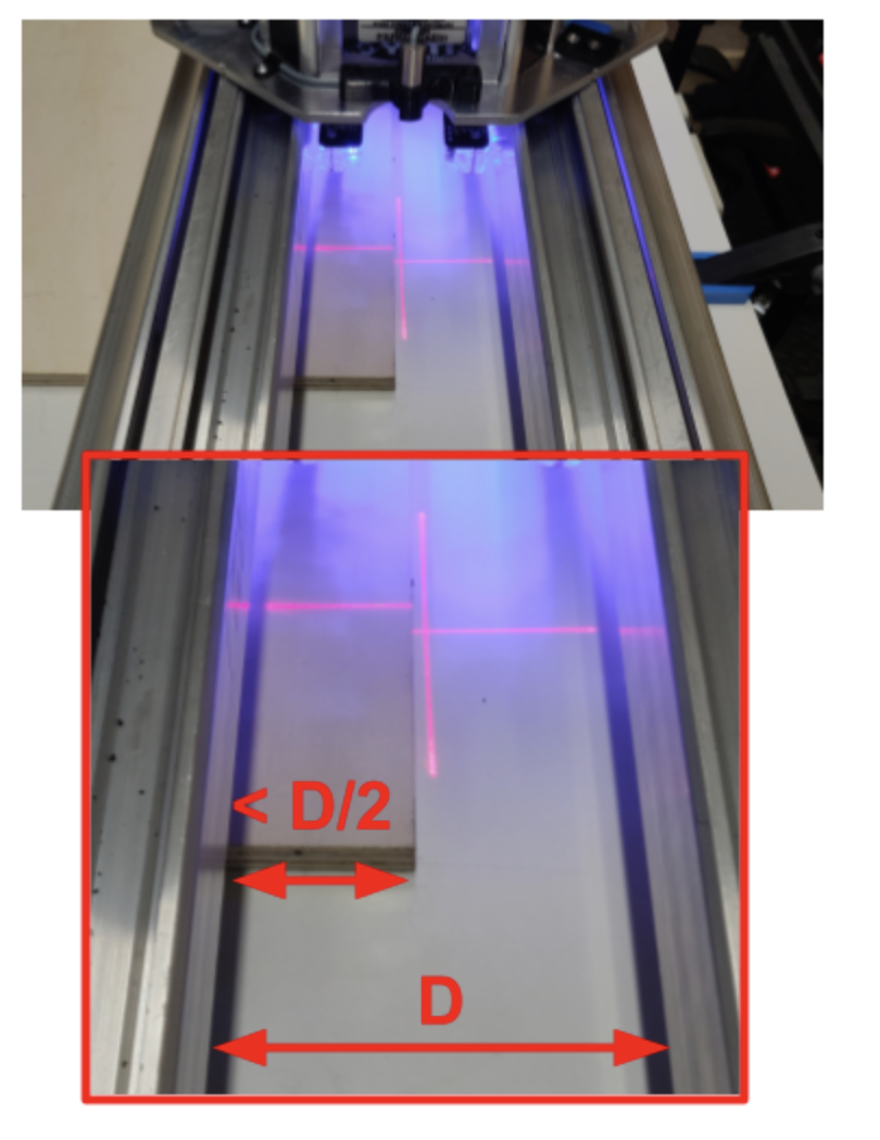
If there is no laser datum installed on your SmartBench, you can use the centre of the tool as a reference point. In the following pictures, we will demonstrate how to do the alignment with the laser crosshair.
Align the laser datum crosshair or tool with one corner of the stock material.
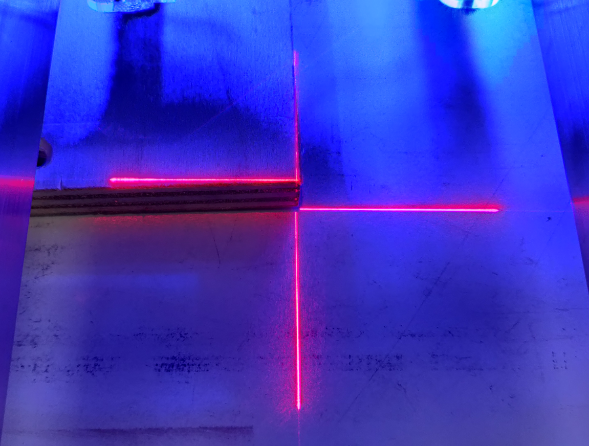
Move the Z Head along the longest side of the stock material to the opposite corner, and check the material positioning.
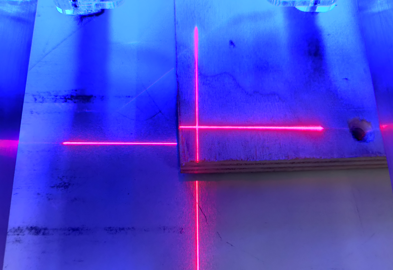
Adjust the positioning as needed.
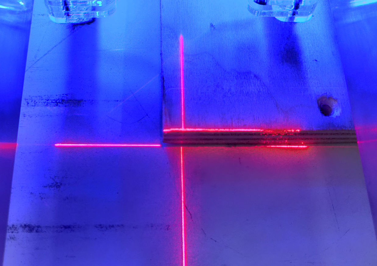
Move the Z Head back to the first corner and check the positioning again.
Repeat the procedure as needed, until both corners are aligned with the tool or laser.
Option 3: referencing the Y Bench
If you don’t use a spoilboard, align the edge of the stock material with the side of the Y Bench using the same tape measure technique as with a spoilboard.
Read the previous section to learn how to position a spoilboard.
Once you are happy with the position of the material, fix it properly to SmartBench. This can be achieved by using:
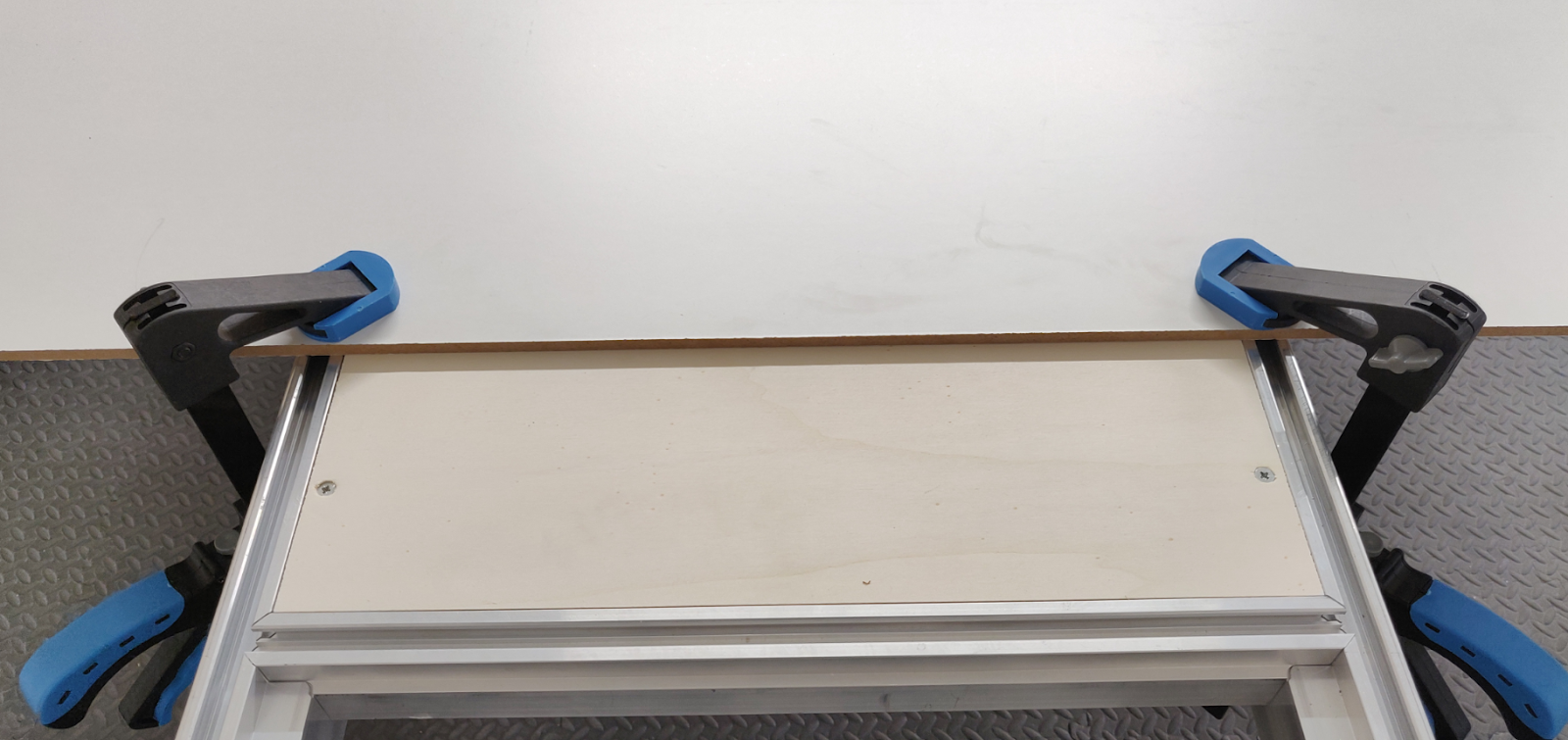
Clamps
On wheel tracks
On Y Bench end plates
On Leg hinge plates
Woodscrews
Into a spoilboard
Into the Y Bench clamp panels
Clamps
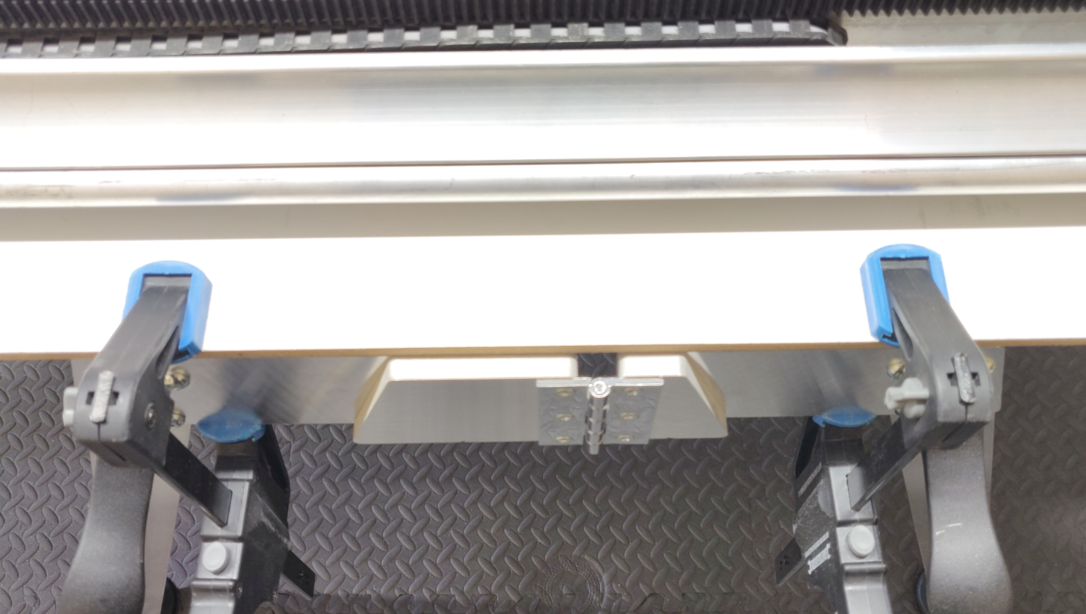
Using clamps is a quick and easy way to fix your material to SmartBench and release it, but this method limits the overall size of a job due to the clamps protruding above the top surface of material.
We recommend using speed clamps (F-clamps). The jaws of these normally have plastic pads, which will not damage SmartBench.
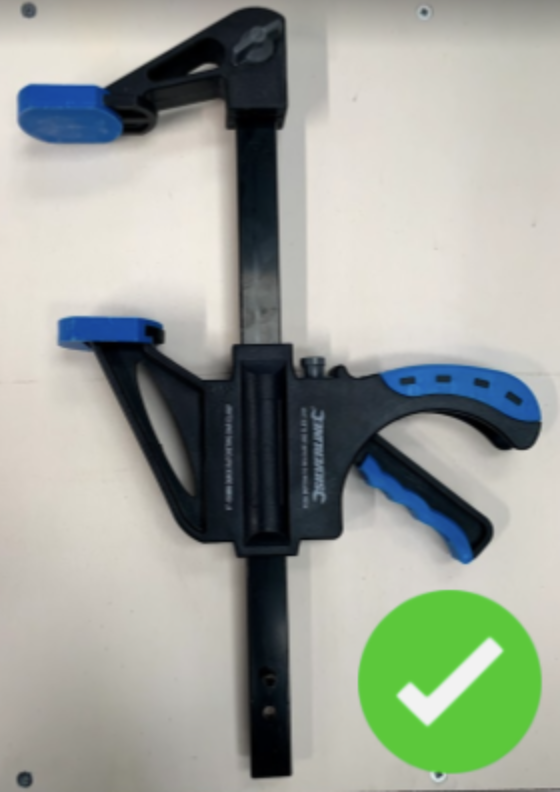
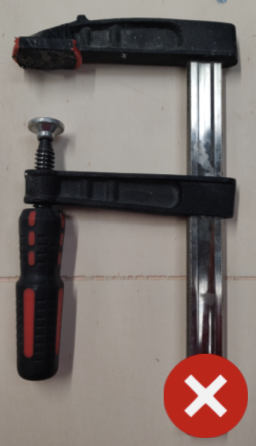
Avoid using G-clamps (C-clamps)! These transfer too much mechanical force and can damage the components of SmartBench. |
Clamp locations on SmartBench
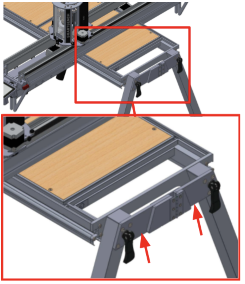
Wheel tracks
Only ever use speed clamps when clamping on to the wheel tracks. Heavier clamps will cause damage to this part of SmartBench. |
End plates of the Y Bench
Leg hinge plates
Where not to clamp
Never clamp in the work zone! The clamps will interfere with moving components of SmartBench. |
Woodscrews
It is possible to fix material directly to the clamp panels (A) of the Y Bench or to a spoilboard under the stock material using woodscrews. Make sure that they are:
Positioned away from the cutting toolpaths to prevent damages to the tool.
Driven at least 1mm below the top surface of the material (provided you are using a spoilboard), so as not to disturb flatness.
Woodscrews
It is possible to fix material directly to the clamp panels (A) of the Y Bench or to a spoilboard under the stock material using woodscrews. Make sure that they are:
Positioned away from the cutting toolpaths to prevent damages to the tool.
Driven at least 1 mm below the top surface of the material (provided you are using a spoilboard), so as not to disturb flatness.
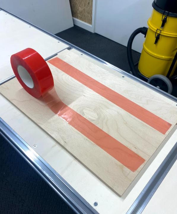
Double sided tape
You can fix smaller materials to SmartBench with double-sided tape.
Make sure your chosen tape has the right properties for your stock material. For example, use woodworking tape to properly fix wood offcuts.
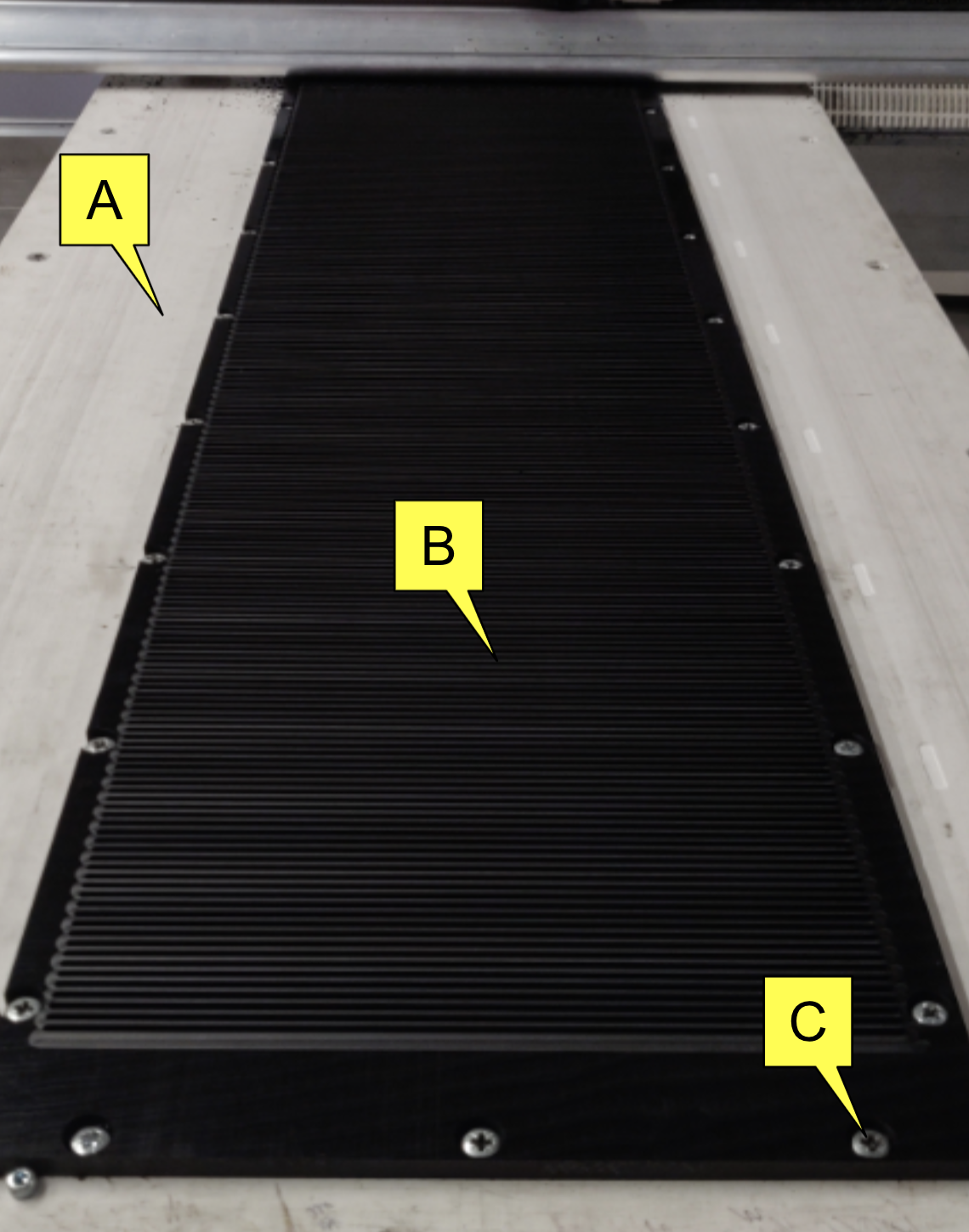
Why does the Upper X Beam need support?
SmartBench needs to consistently clamp the material between the rollers of the Lower and Upper X Beams throughout the job.
Check out the second section ‘What is Smartbench’s material clamping technology?’ to learn more about material clamping technology, and why it is important.
A – Stock material
B – Spoilboard
C – Upper X Beam rollers
D – Lower X Beam rollers

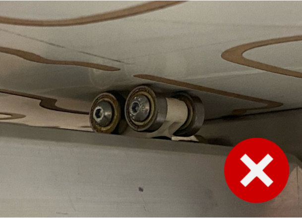
If an offcut sheet material is only just big enough to accommodate the job, the Upper X Beam rollers will move away from the surface of the material during machining.
In this case one side of the Upper X Beam will not be supported, and the X Beam will no longer be fully clamped around the materials.

Methods for supporting the Upper X Beam
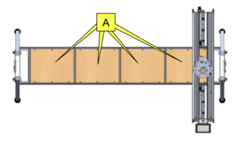
To support the Upper X Beam rollers throughout the job, ensure that there is always some supporting material that sits under the rollers, and extends a minimum of 70 mm from the job boundary along the Y axis.
You can achieve this by:
Choosing a larger sheet of stock material
Adding support tracks around the stock.
Choose a larger stock material
Ensure that the stock has an extra 70 mm of material either side of the job boundary, along the Y axis.
E: Cutting area
F: Minimum stock size

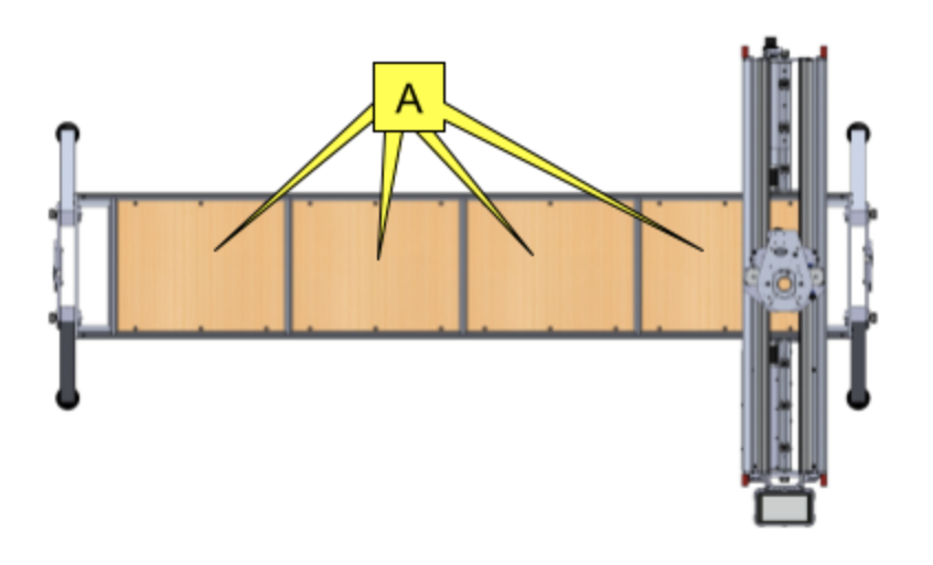
Add support tracks around the stock material
It is still possible to use the same stock material, provided it is used with additional pieces of support material. These additional pieces of support material will form tracks for the Upper X Beam rollers.
The thickness of the tracks must be at least the same as that of stock material, or up to 6mm thicker than stock material. The track material must be flat and hard to prevent the Upper X Beam rollers digging into it.
The length of the support material along the Y axis must be at least 70 mm longer than the stock material on both sides to continuously support the Upper X beam, and wide enough to accommodate the rollers.
G: Additional support material
H: Stock material

During set up, adjust the Upper X Beam rollers so that they run on the tracks.
Imagine the following scenario. You have a sheet of stock material locked to a spoilboard, which, in turn, is attached to the Y Bench. Most likely, the stock material is locked to the spoilboard in just several points; as long as it is a single piece of material, it will not move.
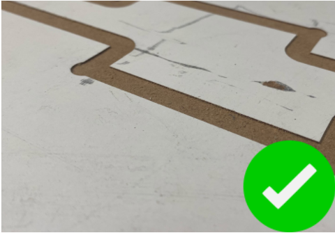
You are cutting a closed contour shape. Once the cutter breaks through the thickness of the material and completes the contour, the piece will not be attached to the material anymore.
If you have more routing to do within the contour, you will be working on a piece of material not locked on the spoilboard and able to move!
What is a tab?
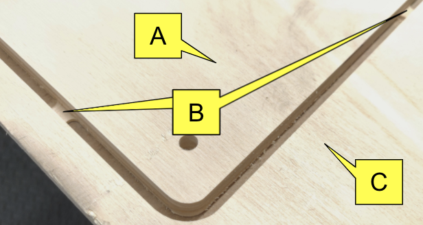
A “tab” is a feature generated by CAD/CAM software and embedded in the toolpath. It keeps the finished piece of a job attached to the stock material, so it cannot move or bend.
After the job is finished, the tabs can be cut or broken.
A: Finished piece.
B: Tab.
C: Stock material.
How do I create a tab?
CAD/CAM software gives you the option to add tabs to the contour cut toolpath. For example, in Vectric VCarve you can set up the size, the number and location of the tabs.
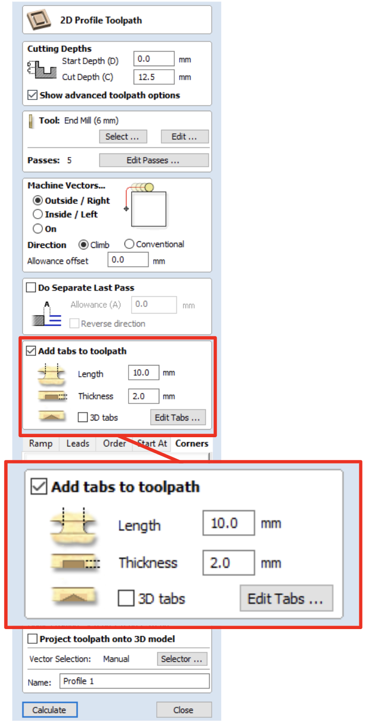
After the contour is finished, the piece will stay attached to the stock material throughout the job. After the job is completed, the tabs can be broken.
How do I break a tab?
Depending on the material, you can use:
Chisel
Utility knife
Saw
What else do I need to know about tabs?
When creating tabs, keep the following in mind:
Create as few tabs as possible; less tab breaking to do after the job is finished.
Do not create tabs in the corners and, if possible, avoid radiuses. If tabs are positioned on the straight segments of the job, it will be easier to cut and finish them.
Create small tabs when possible. It is easier to break smaller tabs, but you need a bigger tab to hold a bigger piece of material.
Align the tabs perpendicular to the grain of material. The tabs will be stronger, but easier to cut.
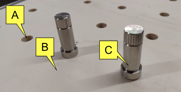
Dogs
Dogs would normally be mounted on the surface of the Y Bench, so will only be suitable for the widths of stock material smaller than the width of the Y Bench.
You can rout the wooden clamping panels of the Y Bench to have holes for the dogs in positions you need.
There are different designs of the workholding dogs available, please explore available options and choose a suitable one.
A: Holes in the clamping panel for dogs fitting.
B: Y Bench clamping panel.
C: Workholding dog.
Jigs
Jig is a good solution for repetitive jobs, where the same size of stock material is used.
We use jigs in the manufacturing of our own racks for SmartBench. The jig is attached to the Y Bench and has threaded inserts. The stock material is attached to the jig with screws.
A: Jig.
B: Stock material.
C: Screw.
Masking tape and superglue
Apply masking tape to the base surface (the spoilboard or the Y Bench) and to the material.
Fix the masking taped surfaces to each other by applying superglue to the masking tape of one surface, and stick both masking taped surfaces together.
A: Material (spoilboard or stock material).
B: Base (Y Bench or spoilboard).
C: Masking tape.
D: Superglue.
Other techniques
You can use any other methods as long as:
The stock material is held in place and not moving.
The moving components of SmartBench do not interfere with the workholding.
What will we do?
In this example we will:
choose our spoilboard
position and align the spoilboard on SmartBench
position and align the stock material on SmartBench
lock both sheets on SmartBench using clamps
Choosing our spoilboard
We will use a large sheet of 9mm coated MDF material for our spoilboard.
read above section ‘What makes a good spoilboard for routing?’ to learn what makes a good spoilboard.
Raising the Upper X Beam
Unclamp and lift up the Upper X Beam, ready to load the material.

Positioning our spoilboard
Load and position the spoilboard on the Y Bench, aligning it using the tape measuring technique.

Read above sections for detailed instructions on how to do this.
Positioning our stock material
We will use a sheet of plywood.
Position and align the material.

Read above section ‘How to position stock material’ to learn how to position and align stock material to the spoilboard.
Locking materials
Use speed clamps to lock both spoilboard and stock material on SmartBench.
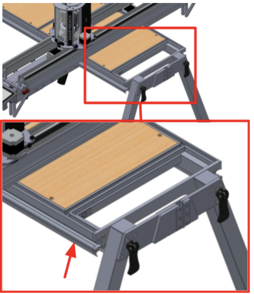
Lock on leg plates at the home end of Y axis.


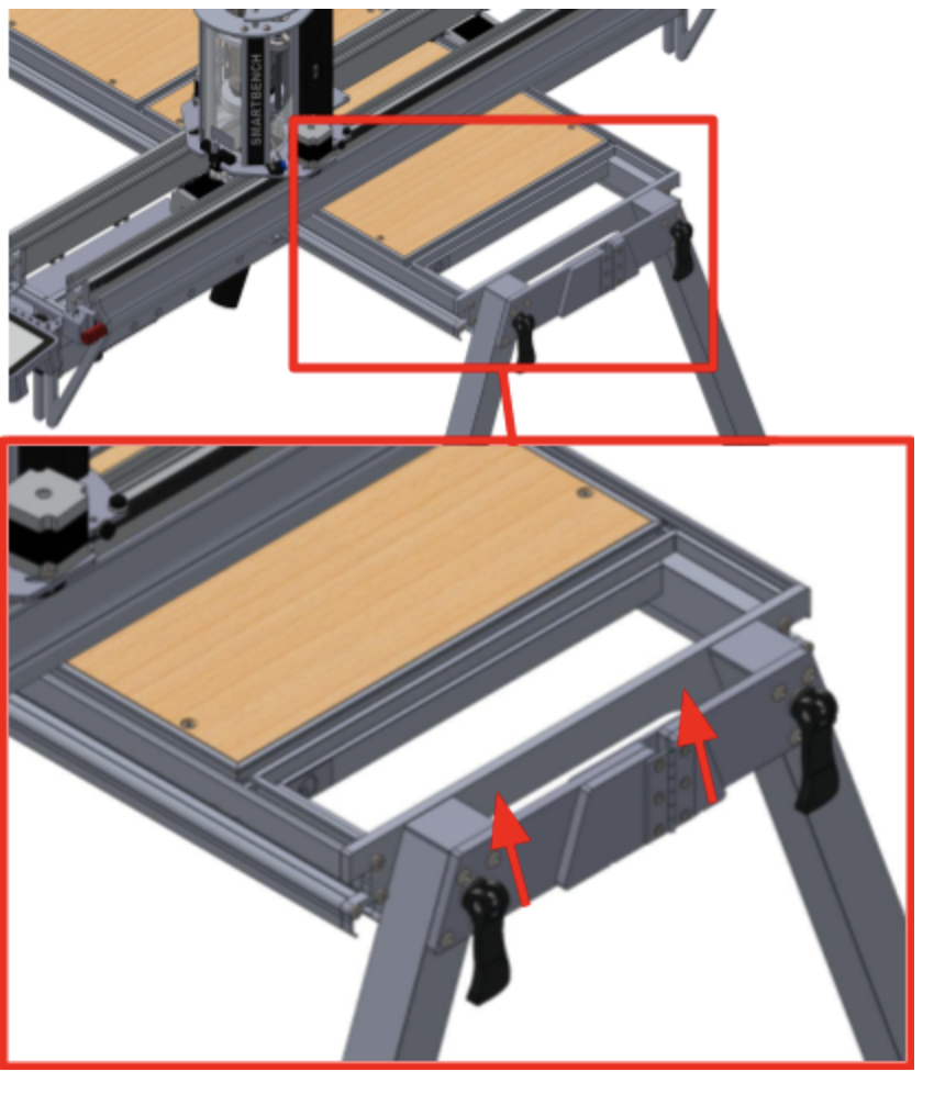
Lock on wheel tracks on the far end of Y axis.


Lower and clamp the Upper X Beam
Adjust the rollers so that they will make full contact with the material as the Beam runs along the Y axis.
Unclamp and lower the Upper X Beam.
Ensure that the rollers are fully resting on the surface of our workpiece, with the full weight of the Upper X Beam distributed evenly through them.

Securely clamp the Upper X Beam onto the Lower X Beam, using the two clamp handles at each end of the X Beam.

What will we do?
In this example we will:
choose our spoilboard
position and align the spoilboard on SmartBench
lock spoilboard on SmartBench
position and align the stock material on SmartBench
lock both sheets on SmartBench using clamps
Choosing our spoilboard
We will use a large sheet of 9mm coated MDF material for our spoilboard.
Read above section ‘What makes a good spoilboard for routing?’ to learn what makes a good spoilboard.
Raising the Upper X Beam
We will unclamp and lift up the Upper X Beam, ready to load our material.
Lift the Upper X beam above the Y Bench high enough to allow both spoilboard and stock material to freely move under it.
Positioning our spoilboard
Read above section ‘How to position a spoilboard’ to learn how to position and align a spoilboard using the tape measure technique.

Locking our spoilboard
We will use speed clamps to lock our spoilboard on SmartBench.
Lock on leg plates at the home end of Y axis.
Lock on wheel tracks on the far end of Y axis.

Positioning our stock material
We will use an offcut of a 12mm plywood sheet and align it with the edge of the spoilboard along the Y axis.
Read above section ‘How to position stock material’ to learn how to position and align stock material.
We need to make sure that the stock material is positioned away from the clamps used to lock the spoilboard.
Move the Upper X beam closer to the speed clamps holding the spoilboard, so there is a gap between the components of the beam and the clamps.

Position the edge of the stock material as shown in the diagram.
This will guarantee that the moving components of the SmartBench will not interfere with the speed clamps during the job.
Move the Upper X Beam towards the far end of the Y axis using manual moves, so that you have full access to the stock material.
The stock material needs to be square with respect to SmartBench (so that the job happens exactly where we expect – not at an angle that might run it off the stock).
Align the stock with the edge of the spoilboard using a tape measure. Measure the distance of the stock from the spoilboard edge at two points along the Y axis.
Adjust the position of the stock material until the measurements are the same.

Locking our stock material
We will use woodscrews to lock our stock material on the spoilboard.
We are using 12 mm stock and 9 mm spoilboard, so the total thickness is 21 mm. We will use 20 mm long wood screws to attach the stock to the spoilboard.
Attach the corners of the stock material to the spoilboard using the woodscrews.

Read above section ‘Principles for locking offcut sheet material’ to learn how to lock offcut sheet material.
Lower and clamp the Upper X Beam
Adjust the rollers so that they will make full contact with the material as the beam runs along the Y axis.
When we lower the Upper X Beam, we need to ensure that the rollers are fully resting on the surface of our workpiece, with the full weight of the Upper X Beam distributed evenly through them.

Securely clamp the Upper X Beam onto the Lower X Beam, using the two clamp handles at each end of the X Beam.