What we will make
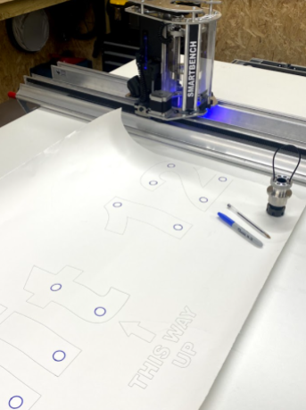
Our project is to make a sign mounting guide. This is a drawing on a large piece of paper (this will allow us to easily drill holes for stand-offs, align and mount the sign on the wall).
Process overview
Here’s a flow chart to illustrate the processes involved, followed by links to each article in this tutorial.

How do I generate the files for SmartBench to draw?
A CAD/CAM package is needed to design the drawing. This package will then export the toolpaths for SmartBench to draw with CNC Stylus.
What CAD/CAM software will this tutorial use?
In this tutorial will design our drawing in Vectric.
Vectric works by:
Defining a general job setup
Drawing out basic features in 2D
Assigning toolpaths to the drawn features
Exporting the toolpaths to a file
We will use 2 different pens, and will export a new file for each of the pens’ toolpaths. This will help us change tools, by allowing us to swap in the correct pen at the start of each job.
Can I use other CAD/CAM packages?
You are welcome to use other CAD/CAM packages to generate the files for drawing. You can use a number of different CAM software packages. Click here to learn more about other CAD/CAM packages which are compatible with SmartBench.
Can I skip this, and just download the files?
Yes! You can download the file made for this tutorial here:
Vectric project file for drawing a sign mount guide (this file is NOT for export to SmartBench. It is to be opened in Vectric. It can then be used to generate job files).
Job file for a sign mount guide – biro (this is a file which was exported and sent to SmartBench).
- Job file for a sign mount guide – sharpie (this is a file which was exported and sent to SmartBench).
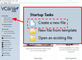
Create a new job file
Start by creating a new file by clicking on Create a new file link.
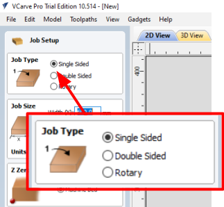
Job type
Select Single Sided, we will only be cutting on one side.
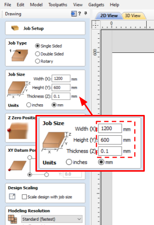
Job size
Specify the minimum dimensions of the stock material you will be using.
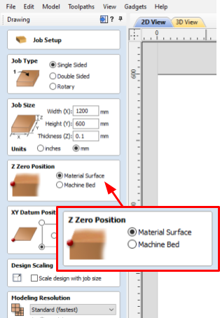
Z datum position
We will use “Material Surface” as Z datum for the job. This means we will be registering the initial position of the tool on the top surface of the material, rather than the surface of the spoil board (for more theory about datums click here).
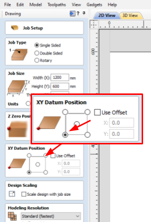
XY datum position
Select the bottom left corner of the bounding box (for more theory about datums click here).
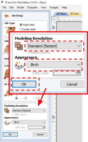
Modelling resolution and appearance
These settings do not affect the cut path and are used only for preview rendering. Select Standard (fastest) from the drop down to speed up the preview rendering of the cut path. Select Birch in Appearance drop down.
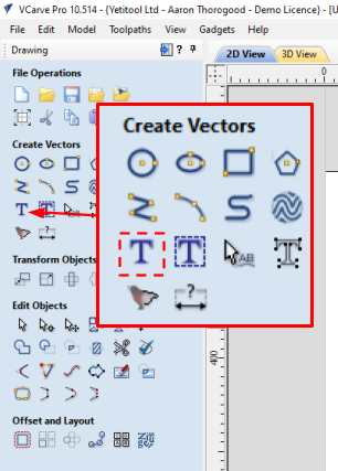
Draw text
First, we will create the text using the same font and size as the sign.
Click on Draw Text
Define the parameters for the text:
Type “Unit 12” in the Text field
Select Arial Black
Select Center for Text Alignment
Type 200 for Text Height

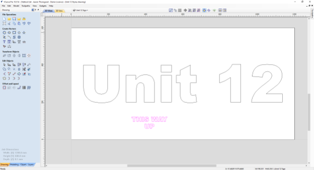
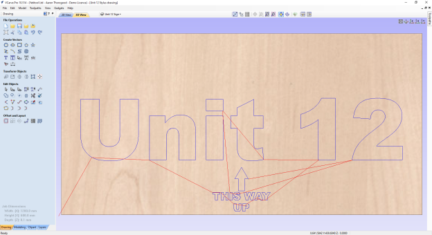
Confirm by clicking on the Close button. The text will appear on the job screen.

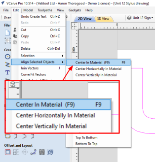
Click on the text, the colour of outlines will change to magenta. Go to Edit > Align Selected Objects > Center In Material

We are now going to add secondary text just like in the previous steps.
Define the parameters for the text:
Type “THIS WAY UP” in the text field. Press ENTER for the new line
Select Center for Text Alignment
Type 25 for Text Height
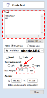
Confirm by clicking on the Close button. The text will appear on the job screen.
We can now align this just as we did before.
To move an object, click on it twice until the object is highlighted in magenta with the anchor points showing. You can use the arrow keys on your keyboard to move the object.

Draw arrow
We are now going to draw the arrow.
Click on Draw Rectangle
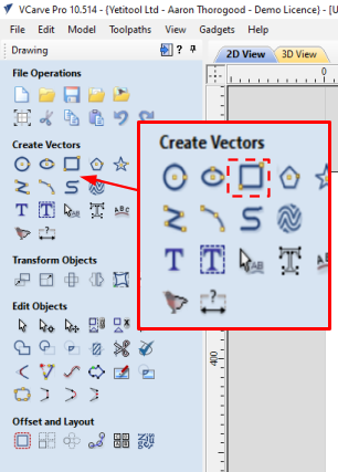
Define the parameters of the rectangle
Width (X): 20mm
Length (Y): 40mm
Corner type: Square

Confirm by clicking on the Create button. The rectangle will appear on the job screen.

Click on the rectangle, the colour of outlines will change to magenta. Go to Edit > Align Selected Objects > Center Horizontally in Material

To move an object, click on it twice until the object is highlighted in magenta with the anchor points showing. You can use the arrow keys on your keyboard to move the object.

We are now going to draw the arrow.
Click on Draw Polygon
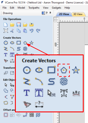
Define the parameters of the triangle
Number of sides: 3
Radius: 25mm
Side length: This will auto-fill calculated by the radius

Confirm by clicking on the Create button. The triangle will appear on the job screen.

Click on the triangle, the colour of outlines will change to magenta. Go to Edit > Align Selected Objects > Center Horizontally in Material
To move an object, click on it twice until the object is highlighted in magenta with the anchor points showing. You can use the arrow keys on your keyboard to move the object.

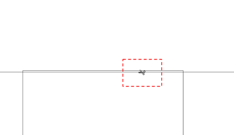
To trim and join vectors (rectangle and triangle), select the Interactive Trim tool
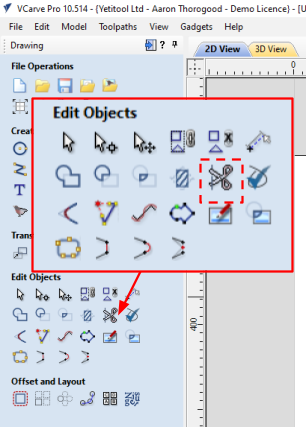
Trim the vectors to join the 2 objects

Draw mounting holes
Next we will draw some circles to act as the mounting holes:
Click on Draw Circle

Define the parameters for the circle:
Diameter: 19mm
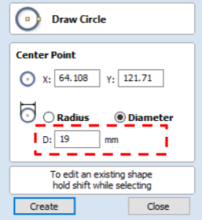
Confirm by clicking on the Create button. The circle will appear on the job screen:
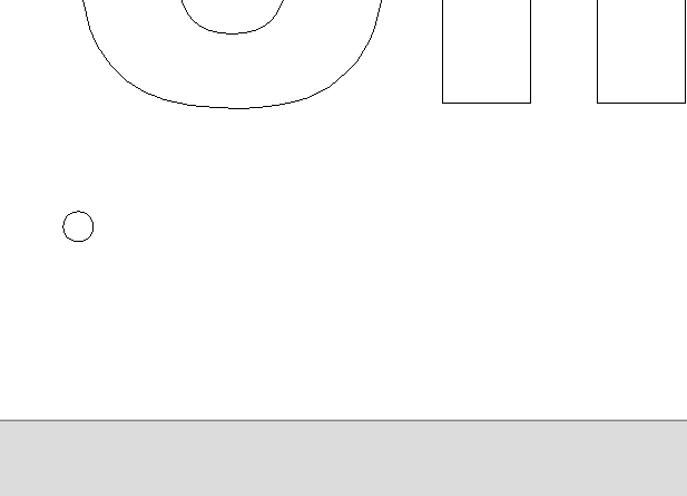
We can now click the circle twice which will highlight it in magenta and show the anchor points. Now, move the circle into place using our mouse to click and drag.

We need to create 17 circles in total. To create a copy, we can select the object and press CTRL + C, and then CTRL + V to paste
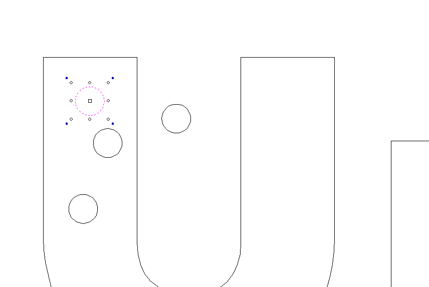
Once you have created all of your circles and moved them to the correct location it should look like this

Overview
In order to create a toolpath in Vectric, you need to provide the software with information about the tool used. Vectric has a database of tools, where you can store setup information about the cutters you use in your jobs. Even if the same tool is used for different types of materials, e.g. hardwood and softwood, you can store essential information about feed rates and spindle speeds in the database, so you can reuse it in your other jobs.
Adding through toolpath setup
When setting up a toolpath in Vectric, you will need to select a tool. In this example we will be using Profile toolpath setup. Click on Select…
The tool database information window with the list of tools already set up will be displayed. Vectric has some tools already in the database.
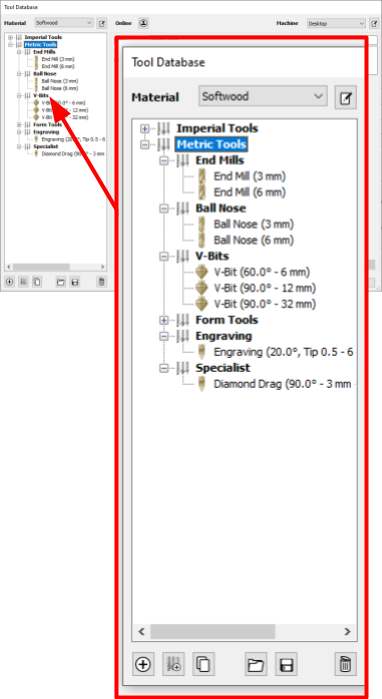
If the tool you require does not exist in the database, you can create a new tool. You can also create a copy of a tool and update its details. In this example we will create a new pen plotting tool.
Select the correct material. In this example we will create a new category for pen plotting.
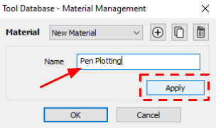
Press the icon to create a new category

Then press the + icon and enter a category name, then press apply and OK.
Select Imperial or Metric tools depending on what cutter you have. In this example we will create a metric tool.
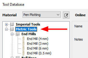
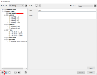
We will then create a new group by pressing the button second from the left at the bottom, and entering the group name “Pens”. We can then press Apply

To create a new tool in this group, select the group and press the + button in the bottom left
In our example we are creating a pen with a diameter of 0.5mm. We will use End Mill as there is not a specific tool type to choose here.
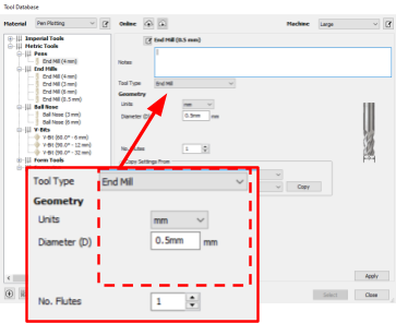
Material specific settings for the cutter can now be created. For a biro, we can use the following settings:
Feed Rate: 6000mm/min
Plunge Rate: 750mm/min

After updating the setting, click on Apply and Select.
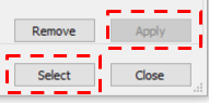
You have now set up a new tool, stored it in the Vectric tool database and applied the tool choice to the toolpath.
Adding through main menu
If your job already has some cutting paths set up, you can add a new tool by going to Toolpaths > Tool Database in the main menu.

Overview
Now the features are drawn in Vectric, we will assign toolpaths. For this tutorial we will assume we are using a biro with a nib diameter of 0.5mm.
Creating a profile for Pen
To draw the first toolpath using a biro, we will first select the profile
Click on the text and arrow outline to select it (hold shift while clicking the mouse) and then click on the Toolpaths tab on the right hand side of the job screen. Select Profile Toolpath.

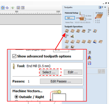
Input the following parameters for Profile
Select a tool (diameter of 0.5mm)
Start depth: 0.0mm
Cut depth: 0.1mm
Machine vectors: Outside/ Right
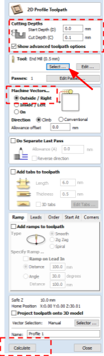
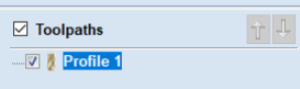
Click calculate. Note that the “Profile 1” toolpath will appear in the list
The preview of the toolpath will also appear in the 3D View tab at the top of the job screen.
Creating a profile for Sharpie
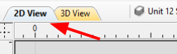
Switch back to 2D view
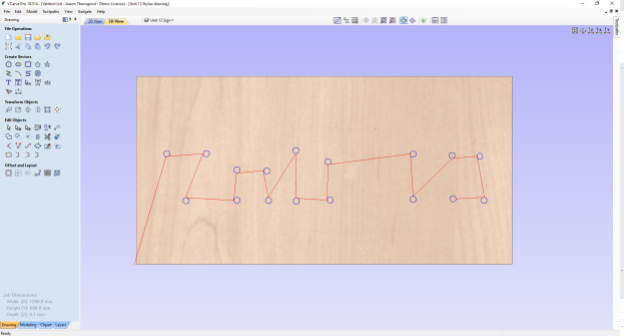
Click on every circle while holding the Shift key on the keyboard to select all of them. Selected circles’ outlines will change to dotted magenta lines.

Click on the Profile Toolpath
Input the following parameters for Profile
Select a tool (diameter of 0.5mm)
Start depth: 0.00mm
Cut depth: 0.1mm
Machine vectors: Outside/ Right

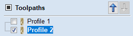
Click calculate. Note that the “Profile 2” toolpath will appear in the list
The preview of the toolpath will also appear in the 3D View tab at the top of the job screen.
The job is now ready to be exported to a G-code file.
Once you create toolpaths, you can export them into a G-code file. Click on Toolpath on the right hand side of the Vectric screen.

You will see a list of created toolpaths.
If the check box next to a toolpath is ticked Vectric will show a preview of this toolpath. Tick on the check box next to Toolpath to select/deselect all the toolpaths.
In this example we will only export a single toolpath into a G-code file.
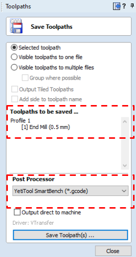
Select the required toolpath in the list and click on Save Toolpath.

Select Selected toolpath radio button. The toolpath selected and the tool used will be displayed under Toolpaths to be saved… Select YetiTool SmartBench in the Post Processor drop down.
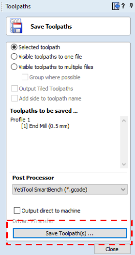
Click on Save Toolpath(s)…
Select the location for the G-code file and its name. By default Vectric will name the file after the toolpath’s name.
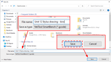
Repeat this for the next toolpath. We will name this Unit 12 Stylus drawing – sharpie
Your G-code file is now ready to be transferred to SmartBench.
How do I transfer files to SmartBench?
You can either transfer files to SmartBench via Wi-Fi or using a USB stick.
Please click this link to find out how to do this.
What drawing tools should I use?
You can use a wide range of tools with CNC Stylus, as long as they are no larger than 16mm diameter.

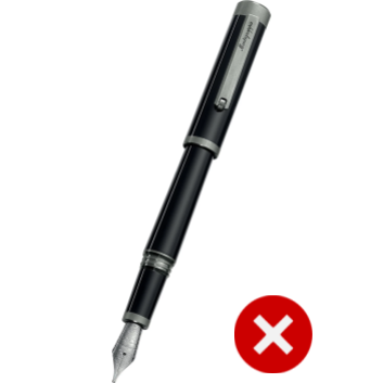
What drawing tools do you not recommend?
We would not recommend using a fountain pen with a metal nib as this could puncture the material.
How long do pens last?
As you may already be aware, pens do not last forever. We suggest that you have multiple pens of the same colour available should it run out during a job.
Fitting and removing a collet
You will need to select the correct size collet for the tool you will be using.
We have created a quick look up table for most standard tools.
Tool | Collet size |
Vinyl Cartridge | 15-16mm |
Sharpie | 11-12mm |
Biro | 7-8mm |
Pencil | 7-8mm |
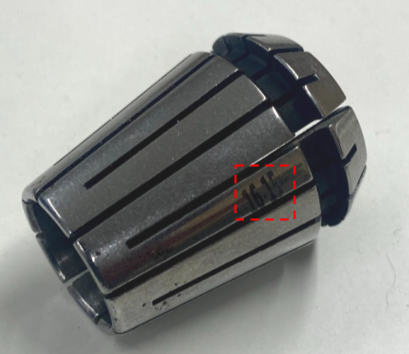
Collet sizes can be found on either the face or the side of the collet.

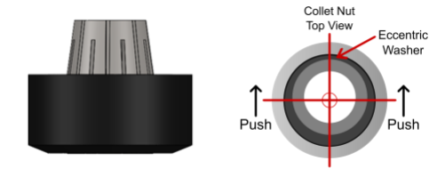
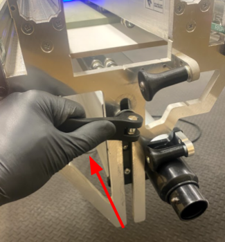
The nut features an eccentric washer which requires force to be applied to a specific side to allow engagement and removal of the collet with the nut.
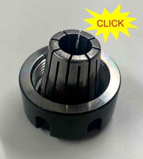
After selecting your collet, you will need to push it into the nut until it engages.
You will hear an audible click. You can check this by inverting the assembly. If the collet is fitted correctly, the collet will not fall out.

To remove the collet, push the collet to the side using your thumb. You may need to rotate the direction of force against the nut.
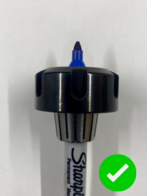
How do I fit a pen into the collet?
Once you have fitted the collet to the nut, you can then insert your selected tool into the collet. This can then be fitted to the CNC Stylus.
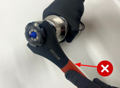
You only need to do this up finger tight.

Please DO NOT use a spanner, as over tightening can damage the barrel thread and the tool.
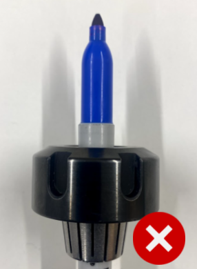
We would recommend holding the tool at the lowest point to reduce wobble.
If you expect to tool change
If you expect a tool change, you will need to consider the position of the pen now, so that your next pen will extend the same distance from the collet. This means that you won’t need to reset your Z datum (SmartBench will expect any new tool to sit at the same offset, unless the Z datum is reset).
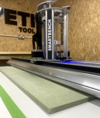
A useful technique to keep pen tip offset the same is to reference the depth of the pen against a known physical feature on SmartBench, for example aligning against the side of the bench extrusion.

How do I choose the correct spoil board?
When selecting a suitable spoil board, we need to ensure to use something
Rigid
Flat
We would recommend using a 12mm melamine faced MDF board.
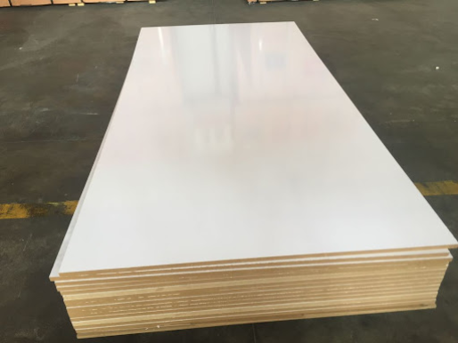
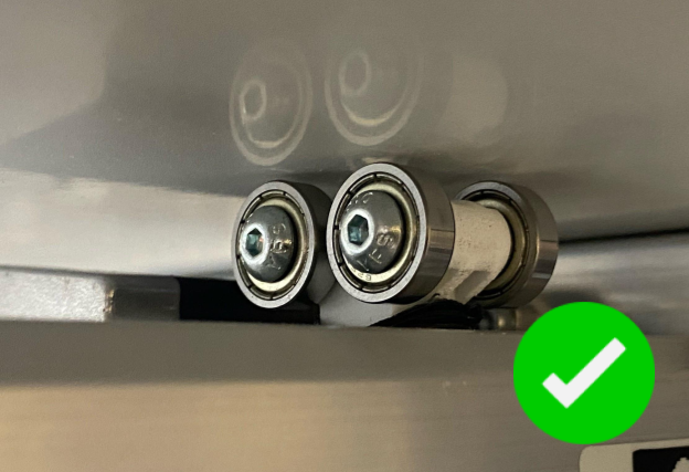
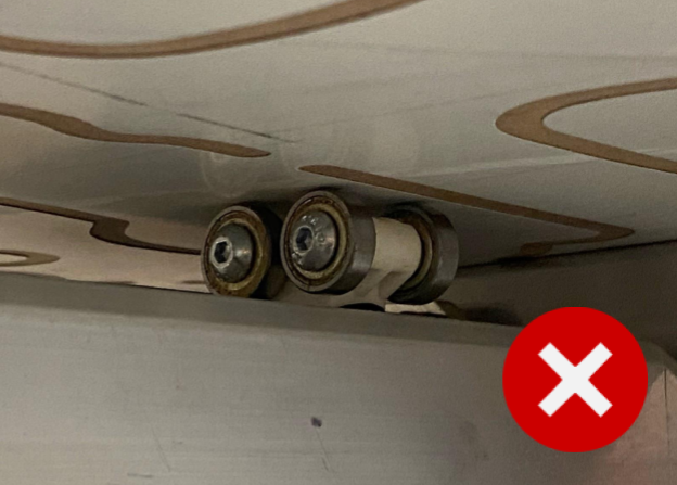
Use a smooth board
The spoil board MUST be new and smooth.

The lower roller wheels need to run along a flat surface to maintain accuracy.
Using tape
There are several different ways to hold material down to your spoil board. You should ensure your material is as flat as possible and that your material does not lift or move.
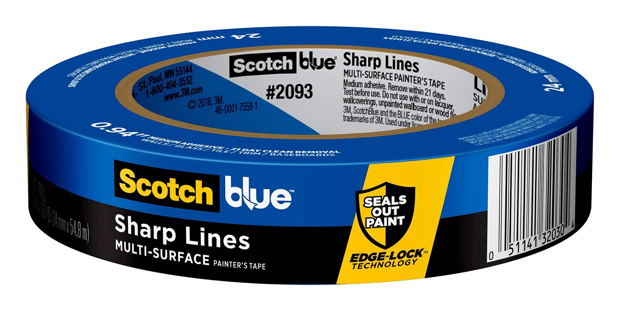
We would recommend using a low tack tape along all edges such as masking tape or Scotch Blue Tape.

Other methods
You can also explore other options, some may work better than others but this is depending on your material and application, one example being spray mount.

Paper resources
We like using background paper as it comes in large rolls. Click here for an example.
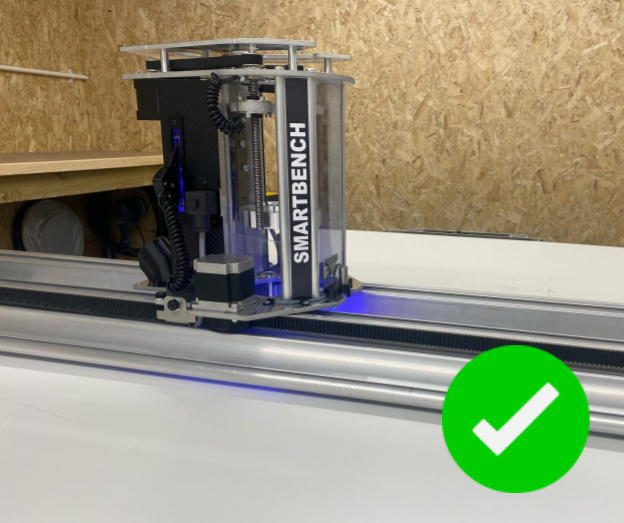
Clamp the upper X Beam above the material
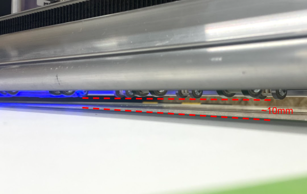
To ensure the wheel units on the upper beam do not crease your drawing material, the upper beam will need to be raised to a fixed position around 10mm above your material.
How do I set the X beam height?
To set the X beam height, loosen the clamp on each end of the upper X beam.

Lift the X beam up so that the wheels are around 10mm from the material ensuring it is parallel. You may want to use a piece of material to set this more consistently.
To secure the beam, retighten the clamp handles.
Fitting CNC Stylus to SmartBench
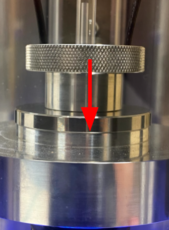
Using the loop, lower the CNC Stylus into the Z Head until the boss sits in the spindle collar.
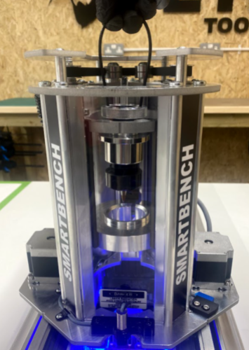
Check that the boss has fully inserted into the collar.
Using the 6mm hex driver, tighten the hex bolt. You should tighten the hex bolt until you feel resistance and then continue to tighten a QUARTER turn.
NOTE: No more than 5nm of torque is necessary.

What does this mean?
We have already set our XY datum in the job file when we made it previously in CAD. Now we need to set an XY datum in SmartBench. This gives SmartBench a reference point to work from.
For more theory about datums click here.
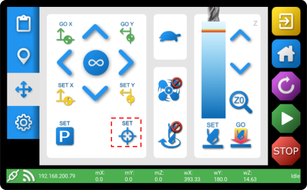
How do I set the SmartBench XY datum using the tool as a pointer?
To set a datum using the tool as your reference point, using the arrows to move the tool to your selected point.

You may need to lower the tool using the Z axis controls

Once you have moved your tool to the correct place, you can then press SET
For further details on how to set an XY datum on Smartbench, click here.
What is a Z datum?
We have already set our Z datum in the job file when we made it previously in CAD. Now we need to set a Z datum in SmartBench. This gives SmartBench a reference point to work from.
For more theory about datums click here.
A Z datum is typically set to the top, or the bottom of the material you are working with. For this tutorial, we are referencing the top. |

How do I set the Z datum with a pen in CNC Stylus?
After fitting CNC Stylus with a pen, and loading into SmartBench, now we need to tell SmartBench where the pen touches the paper. This is the Z datum.
Using the console, we will now lower the Z axis until the pen touches the top of your material surface.
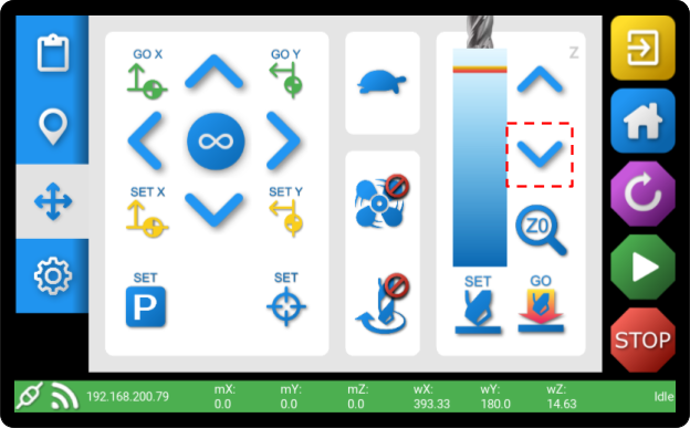
When the pen touches the material, we need to then continue to move the Z axis down by a further 2mm. This puts the pen in the centre of the CNC Stylus’ allowable travel, enabling it to absorb any variation in flatness.
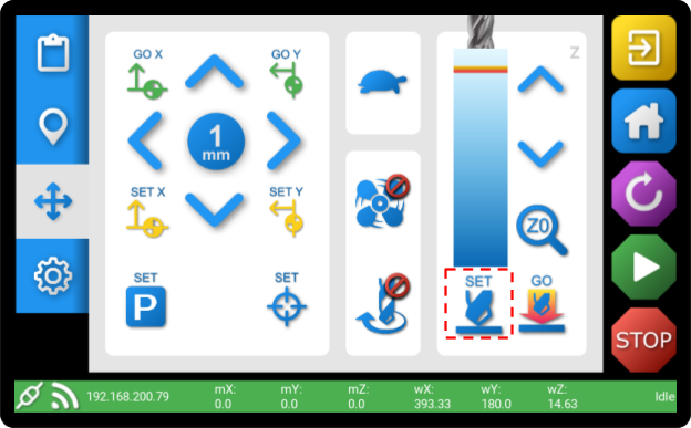
To do this, change the move increment to 1mm…

… and press the ‘Z down’ arrow twice.

You can now press SET to save the datum.
For further details on how to set a Z datum on Smartbench, click here.
Further details
Click here for further details on how to start a job from within the PRO app.
How do I pause the job?
To change the tool, you will need to first pause the job.

How do I change to a new type of tool in the middle of job?
As it is not currently possible to reset the Z datum during a job, you will need to process a job file for each new type of tool you wish to use.
When the job has finished, you will be shown the file completion screen.
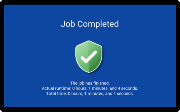
You can then carefully remove your new creation and marvel at your genius.

Pen not run in
Check that your pen is run in. New pens like biros need a quick squiggle on some paper to ensure the ink floods the tip before committing to a job.
Drawing off the boundary
Make sure your paper is cut to the correct size and that you have an extra border to stick your tape too. This will save you from drawing outside of your paper!
Pen wobble
If your pen is wobbling then you may have selected the incorrect size collet, or the pen may be extending too far from the collet.
Pen didn’t contact surface
If your pen is not making constant contact with the surface then you may need to check that you have set your Z height correctly. Also ensure you have a level beam and that your spoilboard is flat and has not already been used for routing.
Pen runs out
Eventually, pens run out. Make sure you have plenty of spares which you can swap out as needed.