Introduction
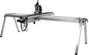
Routing is a process where rotary cutters typically remove material using a sideways action. In SmartBench, the cutter is mounted in the spindle motor, mounted in the Z Head.
A: Spindle motor
B: Cutter
C: Z Head

Router cutter basic elements
A: Shank – this is where the spindle holds the cutter.
B: Flute – for evacuating chips (cut material).
C: Body – this has the cutting edges and flutes of the cutter.
D: Cutting edge – this cuts through the stock material.

Key features
To illustrate some of the features of router cutters, let’s compare them to a more commonly known tool: the drill bit.
 | NEVER use a drill bit in a router spindle! |
Cut process & loading
As a process, routing is very different from drilling. Drilling only cuts at the end face of the drill bit to create holes during a downwards movement, whereas the router cutter needs to cut along the whole side face of the tool to create slots during a sideways movement.
In the following image, the red arrows indicate the cutting directions and areas.
A: Drill bit
B: Router bit

Balance
To manage the higher loading on the tool, the router bit needs to spin an order of magnitude faster.
Here is a chart of typical revolutions per minute (RPMs) for each type of bit:
6mm cutter into timber | Typical RPMs |
Drill | 2,000 |
Router | 20,000 |
Because of this very high RPM rate, router blades must be balanced to a very high degree.
 | Never use a cheap unbalanced cutter in a router spindle. An unbalanced bit in a high speed router cutter will deform to dangerous limits. At best, cut performance will be very bad. Never use a drill bit in a router spindle for the same reason. Typical drill bits are not balanced (since they are designed for low RPMs only). |
Compatibility with SmartBench
The largest cutter shank diameter (A) SmartBench can use is 10 mm for ER16 collets, or 8 mm for OZ collets.

The hole in the dust shoe will accept a cutter body diameter (B) of up to 26 mm (1 inch).
You can use any third party router bits with SmartBench as long as your shank diameter and body diameter do not exceed the maximum requirements.
Click here to see our wide range of compatible cutters from Carbitool Australia.
What is a flute
The troughs between the cutting edges of a routing bit are called “flutes”.
A: Flute
B: Cutting edges (in red)

The flutes have many functions:
The edges of the flutes on the router cutter are designed to cut material (unlike on drill bits).
The angle of the flutes have an important finishing effect on the top and bottom surfaces of the stock material (we’ll cover this later in this guide).
Flutes that are in a spiral or helix shape provide a path for the cut material (chips) to evacuate from the stock material, as the routing bit moves through it.
Unlike drill bits, flutes can push the chips either up, or down, or both up and down simultaneously (forcing chips into the midplane of the stock’s thickness). |
Number of flutes
The most commonly used router cutters have 2, 3, or 4 flutes.
In this section, we will focus on choosing the number of flutes for a spiral cutter, and the effect flute number has on chip evacuation. |
When you use a cutter with more flutes, the channels will subsequently be narrower and shallower. This means that any chips produced in cutting need to be small enough to travel along them. You can make chips smaller by reducing the feed rate.
Red indicates width of flutes, and subsequent maximum chip size:

Flutes evacuate chips from the worktop, and these chips take a significant amount of heat with them. It is therefore important that chip evacuation is as effective as possible. |
Consider your application
The ideal number of flutes will change depending on your application. When choosing a cutter, you should consider:
Material: softer materials need fewer flutes than harder materials.
Surface finish: a cutter with more flutes, and therefore more cutting edges, will result in a better surface finish.
Feed rate: this will need to be adjusted depending on the strength or your cutter, and to allow for effective chip evacuation.
Materials
Use this information as a starting point for choosing your cutters, but also remember that you may want to adjust flute numbers for surface finish, type of material, and the shape of cutter you are using.
Hard materials
Cutters with more flutes work well for harder materials. They tend to have a larger core (due to their geometry), and are therefore stronger than cutters with fewer flutes. This makes them a better choice for harder materials, where you may already be using a slower feed rate and making smaller chips that can travel along the flutes.
For harder materials, consider cutters with 4 or more flutes.

Soft materials
Cutters with fewer flutes work well for softer materials, which the cutter can move through faster, whilst evacuating larger chips through the flutes. However, bear in mind that fewer flutes will result in a rougher surface finish, and the body of the cutter will be weaker.
For softer materials, consider cutters with 2 or 3 flutes.

Fibrous materials
If you are cutting more fibrous materials that create strands use more flutes to reduce the amount of “stringing”.
For a soft plywood, a cutter with 3 flutes would be a good choice.

Feed rates
You may have seen that the rule of thumb is “more flutes more feed”, but this is not always the case. For cutters with lots of flutes, feed rates may even need to be much slower.
A cutter with more flutes is stronger, and will be better at withstanding the forces of higher feed rates.
However, if the feed rate is too high, the flutes will not be big enough to evacuate chips effectively, resulting in overloading of the tool and overheating at the cutting site.
Cutter flute shape
The most common flute shapes are spiral and straight. The following table summarises the pros and cons of both types.
Cutter | Pros | Cons |
Straight |
|
|
Spiral |
|
|
Spiral cutter
Spiral cutters have the flutes ground on a spiral around the cutter body. There are different types of spiral cutters depending on what direction the flutes are cut into the cutter.
Upcut spiral flute


The spiral orientation of flutes is in a clockwise direction (shown in yellow). Chip evacuation is in an upward direction (shown in brown). Material shear is also in an upward direction, which may not create a desired edge finish on the top surface of the cut.
Downcut spiral flute

The spiral orientation of flutes is in an anti-clockwise direction (shown in yellow). Chip evacuation is in a downward direction (shown in brown). Material shear is also in a downward direction, which will create a good edge finish on the top surface of the cut, but not at the bottom.

Upcut and downcut spiral flute (compression)

This is a combination of upcut flutes at the tip of the cuter and downcut closer to the shank of the cutter. That’s a good choice for edge trimming plywood and hardwood.
Straight cutter

A straight cutter has a straight cutting edge. The quality of edge finish on top and bottom surface of the material is lower compared to the spiral cutters.
Straight cutters will not move chips away from the workpiece in the way that spiral cutters do. If using a straight cutter, ensure extraction is optimal. |
Plunge features
Center cutting end mill
A center cutting end mill has cutting edges on both the end face of the cutter and the sides. It can be used for plunge milling (down direction cutting).

Non-center cutting end mill
A non-center cutting end mill has cutting edges on the sides and the cutting edges at the end of the tool do not overlap, which makes it impossible to do a straight plunge. A tool like this can only be used for side milling, if plunging is required it needs to ramp into the material.

Most common types of cutters
End mill cutter

This is the most common milling cutter and is used for most general milling applications. It produces a sharp edge at the bottom of pockets and slots.
End mill cutters can be center cutting or non-center cutting.
Ball end mill cutter
This type produces a radius at the bottom of pockets and slots. Ball end mills are used for contour milling and pocketing applications.

Engraving cutter

Engraving cutters come with a tip angle (included angle) varying from 30° to 90° and are used for contour engraving.
Face mill

This type is a large diameter tool; it is used to cut a wide shallow path for facing operations.
Facing is used for machining a large flat area, typically the top of the part in preparation for other milling operations.
Cutter material
Cutters are normally made of HSS or carbide. The table below shows the advantages and disadvantages of the materials.
Cutter | Pros | Cons |
HSS |
|
|
Carbide |
|
|
Cutters are running at very high speeds cutting into tough materials, so their lifetime is naturally limited. However, a good cutter used correctly will still last longer, and you definitely don’t want to stress out your cutter so much that it breaks mid job!
The factors that can affect cutter life are:
Quality of cutter material
Any specialist coatings applied to the surface of the cutter
Heat produced during cutting
The most common cause of cutter wear is heat. The choice of feeds and speed will determine the amount of heat generated during a job. Read the section ‘Feeds, speeds and direction’ to learn more about setting feed rates and spindle RPM for SmartBench.
Excessive spindle RPM and too slow a feed rate will lead to tool overheating, and (as a consequence) reduction of its life expectancy. |
If adjusting your feeds and speeds has not resolved issues with overheating, you may need to consider a different cutter for your application. Reda the above sections to learn more about number of flutes and cutter types to best suit different applications.
Even without overheating, cutters will still naturally become blunt over time. This is why it’s important to check your cutters in between jobs. We’ll cover how to do this in the next article.
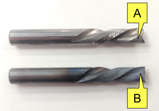
How can I see if my cutter is overheating?
The discoloration of the cutter surface is the main visual sign.
A: Cutter in original good condition.
B: Cutter has been exposed to high temperatures and overheated.

If a cutter is used for multiple jobs, we recommend checking it before every new job.
Using a blunt or damaged cutter will lead to a poor quality cut and overheating (which may damage the spindle motor). |

In this article, we will show you examples of new and worn cutters. The images in this article were taken using a digital microscope.
You can check your cutters by inspecting the edges using a scope (A), or a jeweler’s loupe (B).

Example: New sharp cutter
Firstly, we examine the cutting edge of a brand new cutter. In the image below you can see how sharp the edges are.

Example: Blunt cutter
The surface of the cutter’s material has no discolouration, but the cutting edge is rounded and may not be sharp enough to produce a quality finish cut during the next job.

The same cutter’s cutting edge on the second flute has obvious wear. We recommend replacing the cutter.

Example: Damaged cutter
The cutting edge of another cutter is damaged and the cutter must be replaced.

Example: Discoloured cutter
The cutting edge is still sharp, but discoloration suggests the cutter was overheated. This may lead to unexpected blunting of the cutting edge or even breaking during the next job. The cutter must be replaced.

Due to the manufacturing processes the actual dimension of a cutter can be slightly different from the nominal size.
If you want to use the actual tool size in toolpath generation in a CAD/CAM system, you need to measure the diameter of the cutter.
New cutters normally measure under the specified nominal dimension. Used cutters will measure under the nominal dimension because of wear. |
The method shown here only works for 2 or 4 flute cylindrical cutters.
You will need to use a micrometer.

Take a measurement across 2 points on opposing flutes. Make sure you align the cutter between measurement faces of the anvil and the spindle of the micrometer.


Feeds and speeds are some of the most important factors to consider when implementing any CNC strategy.
You enter the feeds and speeds into your tool settings within your CAM software.
What is feed rate?
Feed rate is the speed at which the cutter moves across the face of the material. It is measured in distance units per minute (e.g. millimetres per minute, or inches per minute).
We will refer to this as our movement speed in X/Y.
What is spindle speed?
Spindle speed is the speed at which your cutting tool rotates. It is measured in RPM (revolutions per minute).
Click here to find out more about spindle specifications, under the ‘What spindle does SmartBench use?’ section.
Which direction should I be cutting in?
Feed direction is defined as either climb milling or conventional milling. Each definition simply describes the direction of the feed against the material, relative to the rotation of the cutter.
You will find this option in your CAM software as you define your toolpath strategies.
Conventional Milling
When the cutter is doing the deepest part of its cut, it is rotating against the direction of the X/Y travel (and is cutting least efficiently).
Note how the width of the chip starts from zero and increases as the cutter finishes slicing.

Climb Milling
When the cutter is doing the deepest part of its cut, it is rotating with the direction of the X/Y travel (and is cutting most efficiently).
Note how the width of the chip starts at maximum and decreases.

Which direction is right for the job?
We would recommend using climb milling on SmartBench whenever possible, because it requires less power to move the cutter through the material.
You may have some scenarios in which you may need to use conventional milling, such as improving accuracy or cutting certain materials.
All of the values in our lookup tables are given using climb milling, so if you need to use conventional milling, then we would recommend reducing your feed rate by around 30% as a starting point. |

What feeds and speeds should I start with?
We have put together some recommended nominal feeds and speeds in order to get you started – you will be able to find the quick lookup tables at the end of this article.
A quick note on Feeds and Speeds Calculators: Traditionally, you would calculate the feeds and speeds for your CNC machine by measuring chip load and using a formula. This approach does not work with SmartBench, so you will need to use the lookup tables as your starting point. |
Remember, this is just a starting point! There are many factors that can have an impact on your feeds and speeds:
Material
Cutter (type, material and sharpness)
Desired surface finish
Desired accuracy
CNC machine characteristics
Extraction performance
Workholding
How do I know if I need to adjust feeds and speeds?
Before you start a job, you need to know when and how to adjust feeds and speeds. This will help you achieve the perfect finish.
If you are trying something new (e.g. a new material or cutter) you can always cut a test piece first on some scrap material, and try adjusting feeds and speeds throughout the test. |
What to look out for
Blunt cutters
You should always check the condition of your cutter to ensure it is sharp and undamaged. Otherwise you might be trying to get the right feed and speed, when you should actually just change your cutter.
Read the above section ‘How to check cutters’ to learn more about how to check your cutter.
Make chips, not dust
When you are honing your feeds and speeds, always look to make chips, not dust. Chips help to take heat away from the stock material, thus increasing tool life and finished edge quality.
Listen to the tool
Always listen to the sound of the tool as it’s cutting. If a router is working too hard you’ll hear it, generally as a higher pitched noise.
If you have a Precision Pro model of SmartBench, you may see the spindle overload begin to increase on the console, normally starting at 20%. If it gets beyond that, it’s definitely time to adjust feeds and speeds!

Overheating on the tool or stock material
Signs of overheating give you an indication of tool damage, or incorrect feeds and speeds. This means your cutter is rubbing rather than cutting.
A: Edge without signs of overheating.
B: Edge with signs of overheating.

A: Cutter in original good condition.
B: Cutter has been discoloured due to overheating.
Problem solving
Here is a problem solving map to help you if you start to have issues.
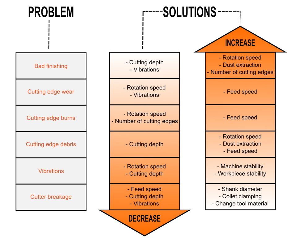
Image credit: CMT Orange tools
How to make adjustments to feeds and speeds mid-job
SmartBench gives you the ability to adjust your feeds and speeds at any time during the job. These can be changed in 5% increments to allow for fine adjustment.

Feeds and speeds: Quick lookup tables
We have tested a range of tools with a variety of common materials. We experimented with different feeds and speeds, and settled on some ballpark starting points.
This data is intended for a new SmartBench user.
Be aware that there are multiple factors to consider when choosing feeds and speeds. The figures shown below are starting points, and you must be able to adjust from these points as required. If you skipped the rest of this article to go straight to this section, make sure you go back and read the previous sections, so that you can adjust as needed. |

MDF
YetiTool Part Number | Diameter (mm) | Shank (mm) | Type | Maximum Step Down/Step Over (mm) | Recommended Feed rate (mm/min) | Recommended Spindle Speed (RPM) |
20805 | 3 | 8 | Upcut Spiral | 1.5 | 2,000 | 18,000 |
20806 | 6 | 8 | Upcut spiral | 3 | 2,500 | 20,000 |
20807 | 8 | 8 | Upcut spiral | 4 | 3,000 | 22,000 |
20813 | 3.2 | 8 | Round Nose | 1.6 | 2,000 | |
20814 | 6 | 8 | V-Groove | 2 | 2,000 | 20,000 |
Plywood
YetiTool Part Number | Diameter (mm) | Shank (mm) | Type | Maximum Step Down/Step Over (mm) | Recommended Feed rate (mm/min) | Recommended Spindle Speed (RPM) |
20805 | 3 | 8 | Upcut Spiral | 1.5 | 3,500 | 18,000 |
20806 | 6 | 8 | Upcut spiral | 3 | 3,000 | 20,000 |
20807 | 8 | 8 | Upcut spiral | 4 | 3,000 | 22,000 |
20813 | 3.2 | 8 | Round Nose | 1.6 | 2,500 | |
20814 | 6 | 8 | V-Groove | 2 | 2,500 | 20,000 |
Softwood
YetiTool Part Number | Diameter (mm) | Shank (mm) | Type | Maximum Step Down/Step Over (mm) | Recommended Feed rate (mm/min) | Recommended Spindle Speed (RPM) |
20805 | 3 | 8 | Upcut Spiral | 1.5 | 3,500 | 18,000 |
20806 | 6 | 8 | Upcut spiral | 3 | 3,000 | 20,000 |
20807 | 8 | 8 | Upcut spiral | 4 | 3,000 | 22,000 |
20813 | 3.2 | 8 | Round Nose | 1.6 | 2,500 | |
20814 | 6 | 8 | V-Groove | 2 | 2,500 | 20,000 |
Hardwood
YetiTool Part Number | Diameter (mm) | Shank (mm) | Type | Maximum Step Down/Step Over (mm) | Recommended Feed rate (mm/min) | Recommended Spindle Speed (RPM) |
20805 | 3 | 8 | Upcut Spiral | 1.5 | 300 | 18,000 |
20806 | 6 | 8 | Upcut spiral | 3 | 400 | 20,000 |
20807 | 8 | 8 | Upcut spiral | 4 | 600 | 22,000 |
20813 | 3.2 | 8 | Round Nose | 1.6 | 300 | |
20814 | 6 | 8 | V-Groove | 2 | 300 | 20,000 |
Plastics
YetiTool Part Number | Diameter (mm) | Shank (mm) | Type | Maximum Step Down/Step Over (mm) | Recommended Feed rate (mm/min) | Recommended Spindle Speed (RPM) |
20805 | 3 | 8 | Upcut Spiral | 1.5 | 2,000 | 18,000 |
20806 | 6 | 8 | Upcut spiral | 3 | 2,500 | 20,000 |
20807 | 8 | 8 | Upcut spiral | 4 | 3,000 | 22,000 |
20813 | 3.2 | 8 | Round Nose | 1.6 | 2,000 | |
20814 | 6 | 8 | V-Groove | 2 | 2,000 | 20,000 |
Aluminium 6082
YetiTool Part Number | Diameter (mm) | Shank (mm) | Type | Maximum Step Down/Step Over (mm) | Recommended Feed rate (mm/min) | |
20538 | 6.35 | 6.35 | Upcut Spiral | 0.8 | 460 | 16,000 |
Composites
YetiTool Part Number | Diameter (mm) | Shank (mm) | Type | Maximum Step Down/Step Over (mm) | Recommended Feed rate (mm/min) | Recommended Spindle Speed (RPM) |
20815 | 18 | 8 | ACM | 2 | 800 | 16,000 |